Sunday, January 27, 2013

NTSC line numbers explained in detail

I've finished examining the NTSC video signal from a vertical line perspective and believe that I understand it as well as I would ever need to for Dexter/Daphne-related problems.

I will now document what I've learned so that when I forget it, I can refer back to this blog post :)

Here is the even->odd field transition:


This is straightforward.  The VBI is 20 lines long (lines 1-20), making line 21 the first "visible" line.  Technically, the visible lines are 21-263.5; however, in practice, lines 22-262 may be considered the 240 lines that NTSC is commonly associated with.

And here is the odd->even field transition:


This is the tricky one and I am going to describe it according to how I visualize (not necessarily how other people describe it).

At the very end of the odd/top field is half of line 263.  Then the VBI for the even field starts (if you assume it starts when the pre-equalization pulses start) and could be considered 20 lines long.

The result is that the vsync pulses will be exactly 262.5 lines apart from each other and thus have a stable frequency.  This is pretty useful to know.

The 525 total lines may be split up like this:

1-20: 20 non-visible lines
21-263.5: 242.5 visible lines
263.5-283.5: 20 non-visible lines
283.5-525: 242.5 visible lines

So the interval from even->odd may be slightly shorter than the interval from odd->even.  Weird.

Therefore, it may be useful to imagine that the VBI period is 20 lines long for both odd and even.

Thursday, January 24, 2013

NTSC even->odd field transition explained in detail

I've done some more oscilloscope captures this morning to try to better learn how NTSC works.  And this has proved incredibly helpful.

First I captured two lines from the LM1881, the vsync and the even/odd field lines.

Here is how they turned out:

Odd field ending, even field starting:


Even field ending, odd field starting:

Once I got this far, I noticed that the LM1881's vsync pulse is a slightly different width depending on whether the field is even or odd.  This gave me the confidence to start capturing the actual NTSC video and making notes because it allowed me to establish quickly whether I was looking at an even or an odd field transition.  In retrospect, I could've just captured the even/odd line instead of the vsync line.  Oh well!

As you can see, I basically took notes on everything interesting about this transition.  It turned out to be the even->odd field transition which is line 1 of the picture, so it is probably a good place for me to start.  (yes, line 1 is the first line, not line 0!  I got confused about this due to my computer science background)


A few handy things to note that I did not notice earlier when reading other NTSC materials:

The vsync pulse period aligns perfectly with horizontal line numbers.  So it is very easy to find the boundaries.  If you just looked at it without knowing this fact, you might get very confused (I sure did!).

Also, the non-visible lines start on line 10.  Line 11 is used by laserdisc for the "white flag" line.  Neat, eh?

Wednesday, January 23, 2013

Got oscilloscope, captured NTSC signal

Yellow = LM1881 vsync pulses (low means vsync is active)
Red = ntsc signal

(they are scaled differently for easy viewing!)

the above image shows a complete NTSC field, plus the beginning of the next field.

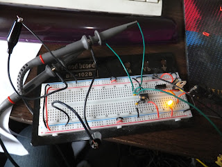
Here is my breadboard setup (with LM1881 in the middle).

The above image shows the beginning of an NTSC field.  The left is the vsync pulse, the middle is the hidden VBI lines, and the right is the beginning of the visible lines (which are all black).

Tuesday, January 22, 2013

R-2R success! (or "How To Use SPICE")

I stopped trying to figure out equations to predict voltage levels for my R-2R experiments and just broke down and learned enough of SPICE to make it show me the answers itself.

Both of these are exactly the same except for the top resistor.  Here is the SPICE program to compute the voltages for the left configuration:


My dang problem
v1 1 0 dc 5
rA 1 2 220
rB 1 3 220
rC 2 0 47
rD 3 0 220
rE 2 3 110

.DC v1 5 5 1
.PRINT DC v(1) v(2) v(3)

.end

It outputs this line:

--------------------------------------------------------------------------------
Index   v-sweep         v(1)            v(2)            v(3)            
--------------------------------------------------------------------------------
0 5.000000e+00 5.000000e+00 1.122611e+00 1.811306e+00

As you can see, v2 (1.122V) and v3 (1.811) match up to my physical readings quite nicely.

Now if I change the SPICE program so that rC is 115 ohms instead of 47, I get this:

--------------------------------------------------------------------------------
Index   v-sweep         v(1)            v(2)            v(3)            
--------------------------------------------------------------------------------
0 5.000000e+00 5.000000e+00 1.916667e+00 2.208333e+00

Again, v2 (1.9166) and v3 (2.21) match up with my results (on the right-hand side of the picture) quite nicely.

Phew!  What a pain in the neck!  I am logging this here so I don't ever have to figure it out again.

To execute these programs, you do the following command:

ngspice -b your_src_file_here.txt

And here is a variation on the program:

My dang problem
v1 1 0 dc 5
rA 1 2 220
rB 1 3 220
rC 2 0 115
rD 3 0 220
rE 2 3 110

.control
set hcopypscolor=1
tran 1us 500us
hardcopy test-tran.ps v(1) v(2) v(3)
.endc

.end

This dumps out the following text:

Initial Transient Solution
--------------------------

Node                                   Voltage
----                                   -------
1                                            5
2                                      1.91667
3                                      2.20833
v1#branch                           -0.0267045

It also writes out a postscript file called test-trans.ps which graphs the voltages, which is kind of useless for my purposes since my voltage does not change.  But it might prove handy later.  The "initial transient solution" data that it prints out is handy nonetheless and in a slightly different format (ie better) than what is printed out in the first program.

To convert the postscript file to a .png, do this command:

convert -background white -layers flatten test-tran.ps test-tran.ps.png

See https://wiki.ubuntu.com/From_PSpice_to_ngspice-gEDA for some more help and some decent "getting started" type explanations.

Monday, January 21, 2013

Current measured over R-2R

In a further effort to understand the R-2R, made a simple one and measured the current:

What I still can't understand is how I could predict those current values without measuring them.  R1, R2, and R4 do not seem to be in parallel or series so I have no equations to start with.

Sunday, January 20, 2013

R-2R resistor ladder experiments

Lately I've been getting interested in generating an NTSC video signal from scratch.  In order to do this, I need a DAC.  But I am not ready to buy a good quality DAC (especially since the one Warren pointed me to was a surface mount!) so I thought I'd mess around on my breadboard with a simple DAC known as an R-2R resistor ladder network.

Actually, before I experimented with this on my breadboard, I tried to figure out how it worked on paper and I got confused.  So I arranged it on my breadboard to try to help me understand how it worked better by measuring the voltages at various junction points.  I have a better understanding now but still need more info to start generating an NTSC video signal.  I am hoping someone more expert than I can help me understand the math involved to finally learn how this dang thing works.

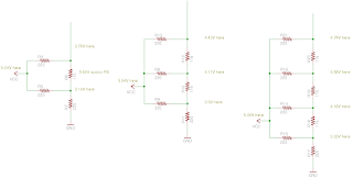
Here are some schematics that represent my experiments.

220 and 115 ohm resistor experiments

I started off using 220 and 115 ohm resistors (230 ohm resistor was not available from digikey so I approximated).  This is based on advice I found on this page (I am going to try building on of those things once my PCB from BatchPCB shows up).  Although they expert the source to be 3.3V, I was curious to see what would happen if my source was 5V.

Here are the results of my experiment:


First, let me explain a few things.  In the setup on the left, I have two source bits (I'll call them D0 and D1) and both are set to "1" (5.04V).  So this represents a 2 bit DAC that has 4 possible values (0, 1, 2, and 3).  You will notice that the maximum voltage is 3.79V here.  This confused me greatly until I re-read the wikipedia page and found this formula:

Vout = Vref × VAL / 2N

What this means is that for a 2 bit DAC, the maximum output voltage can only be 75% of the output voltage.  Why?  Because 2^2 is 4, and the maximum value (VAL in the equation) is 3.  So 5.04 * (3/4) is indeed 3.78V;  conclusion?  Trying to use a 2-bit DAC is a crappy idea :)

You will notice that as I add bits, the maximum voltage increases.  In the middle layout, where I have 3 input bits (again all 1's), the maximum voltage is 4.43V .  2^3 is 8, so 5.04 * (7/8) is 4.41V so we are pretty close.

On the right layout, I have 4 bits, and the maximum voltage is 4.74V.  5.04 * (15/16) is 4.725V so we are still pretty close.

4.7k and 10k ohm resistor experiments

It turns out that the resistor values themselves don't seem to matter much as long as they are approximately 2:1 to each other for the type of experiment that I am doing.

I got almost the same results using 4.7k and 10k resistors:


How to output to a range of 0V-1V for NTSC signal?

So, this is what I am still trying to figure out.

I've seen that TV's are supposed to have an internal 75 ohm resistor.  And apparently it is possible to use this fact and choose resistor values in one's R-2R network such that the resulting voltage is between 0-1V so that it is in spec for a TV signal.  On this page, it says: "the resistor values are chosen to turn the 3.3V of the Papilio output into the 0, 0.3 and 1.0V under 75 ohms that the tv requires."  but I don't understand how they figured out which resistor values to use!

Also, on this page, the guy is using 450 and 900 ohm resistors with a 5V source (although he isn't quite doing the same layout I was).  So obviously there is some math here that I am missing.  If someone could enlighten me, I would be grateful!


Sunday, January 13, 2013

LDM-G1000 programming manual scanned in

A very kind soul mailed me this programming manual last week and I have finished scanning in the entire thing.  This manual has very extensive documentation about how to program the newer Sony laserdisc players such as the LDP-1450, including verbose information about how the text overlay works (which is what I've been working on lately).  I am pleased to say that most (all? hehe) of my conclusions were correct.

You can grab the manual (for a limited time) from here:

http://www.rulecity.com/browsetmp/LDM-G1000/LDM-G1000-Manual.7z

Friday, January 11, 2013

Zooming in on LDP-1450 overlay details

I should have the programming manual for the LDP-1450 today.

Meanwhile, I've done some pretty detailed captures:


So the imaginary grid is 27 characters across, and each character is 16 pixels wide (internally), then that means the internal horizontal grid is 27*16 (432) pixels wide.  Plus we have some black areas on the left and right to account for.  Assuming my measurement of the blue background being 712 pixels wide is correct within 1 pixel, that means it accounts for 712/720 or 98.8888% of the horizontal space.  So if we take 432/.9888 we get 436.85 pixels across as a "native" resolution to render at (I earlier calculated this number at 441 so I am now revising my earlier calculation).  That means we could choose 436 or 437 pixels since we can't use fractional numbers.

Just to double check my calculations, I am going to try arrive at this same conclusion via a different path.
If 20 characters are 526 pixels wide, that means 1 character is 26.3 pixels wide.  And if each character is 16 pixels wide internally, that means that the scaling rate is 26.3/16 (1.64375).  Taking the total screen resolution (720) and dividing by 1.64375 gives us 438.02 as the native resolution to render at.  This is a bit off from my above calculation.  So what if we say that 20 characters are actually 527 pixels wide; then each character becomes 26.35 pixels wide which means the scaling is 1.646875 and the native resolution is 437.2 which is closer to what we arrived at above.

I know that I am close.  The native resolution I should render at is somewhere between 436-438.  All I need to do now is write some code to actually do the rendering and then play around with adjusting this value until I find something close to what I am getting with my captures.

Wednesday, January 9, 2013

LDP-1450 coordinate system

I've got a pretty good preliminary idea of how the coordinate system works for the LDP-1450, at least the relative coordinate system.

The difference in each coordinate step is 25% of the total character size.  So if one character is 32 lines tall (which it is without any scaling), then a vertical coordinate of 0 will show no portion of the character, a vertical coordinate of 1 will show the bottom 8 lines of the character, vertical coordinate of 2 will show the bottom 16 lines of the character, etc.  NOTE that coordinate 0 will show the bottom grey part of the character if the shadowed edges are enabled, but otherwise will show nothing.  This may be an unintended design flaw.

Horizontal coordinates are the same idea but it is more difficult to represent them as pixel shifts since they don't map 1:1 to pixels.  We can safely say that incrementing the horizontal coordinate by 1 will shift all characters to the right by 25% of their total width.

I am pretty sure that this is true no matter how scaled the character is (ie it remains a 25% step) but I have not yet had a chance to verify this.

Tuesday, January 8, 2013

Bits from LDP-1450 text mode understood better


After capturing yesterday's video, I have examined some of the screenshots in GIMP, and have come up with a pretty strong theory about what each bit means.

Bits 0 and 1 (range 0-3) mean the following:

00: horizontal default size (~26 pixels wide when captured at 720x480)
01: horizontal size * 2
10: horizontal size * 3
11: horizontal size * 4

Bits 2 and 3 are like 0 and 1 but apply to vertical scaling:

00: vertical default size (32 lines tall)
01: vertical size * 2 (64 lines tall)
10: vertical size * 3
11: vertical size * 4

Bit 4, if 1 means display text in a 10x3 grid.  If 0, text is displayed on 1 line and may have a limit of 20 characters (unconfirmed).

Bit 5 means surround letters with a grey border.

Bit 6 apparently has no effect unless bit 5 is also set; if both are set then the text will have a solid grey background (like when the current frame number is displayed).  The grey will be above and to the right of each character, unlike the grey border which is uniformly around each character.  I will need to do further investigation to see if this makes the character offset at all or if it is the grey part that is offset.

Bit 7 (if set) means that the laserdisc video is replaced with a light blue background which is handy for testing this stuff as it makes the letters clearer.

And I also found someone who has the programming manual for the 1450 (and other newer Sony players) and he has tentatively agreed to mail to me.  So I can get a more excellent idea of how the X/Y offsets work plus one other setting that I have (up to this point) completely ignored.

Monday, January 7, 2013

All the LDP-1450 text modes explored


I wrote a program to rapidly cycle through all possible text modes for the LDP-1450 laserdisc player.  The mode number is in hex and comes right after the 'M'.  X and Y position is fixed at 10x10 (0Ax0A in hex).  The trailing characters are leftover from earlier tests, but this illustrates that the entire text buffer must be cleared out or else it will be displayed.

NOTE : in order to display modes when a blue background is not present, a disc must be playing.  (if no disc is in the machine, it won't show anything)


As you can see, this is very helpful in determining what each bit of the mode byte means.  I haven't dug into this much yet but it is pretty apparent that some bits represent width and some bits represent height.

Sunday, January 6, 2013

Preliminary algorithm discovered for LDP-1450 text

I've discovered a preliminary algorithm for rendering LDP-1450 overlay text which will probably undergo a lot of tweaking as I study the different modes that the text can be rendered in.

But if the text is rendered in the mode that Dragon's Lair 2 uses, here is a pretty close approximation (pretty close meaning it is within 1 pixel of being perfectly aligned with the original capture).

Here is the original capture I just made:


First of all, I should mention that I am quite sure that each character is stored internally (in the LDP-1450) as a 16x16 bitmap.  When it is rendered in the above mode from the capture, it is stretched vertically by a factor of 2 (so every character is 32 lines tall).  Attempting to render a character in a multiple other than 16 would require complex graphics hardware which is probably beyond the technology available when this player was made (or at least it would've been very expensive) so it is safe to assume all rendered characters must be either 16, 32, or 48/64 lines tall (so far I have only encountered 16 and 32 lines tall).  If I am wrong about this, I will be very surprised (but I will still find it very interesting).

The horizontal stretching is another matter.  In the case of this capture, each character is about 25 or 26 pixels wide, so it scales about 1.625x or 1.5625x.  I decided to measure a whole row of characters to try to get a more accurate scaling factor and found that an entire row of 10 characters is about 261 pixels (internally this would be 160 pixels), so each character is about 26.1 pixels wide.  This means that the actual scaling factor is about 1.63125 ;  so we take the total width (720) and divide by this number and end up with 441.379 pixels as a "native" resolution in which we can write characters that are 16 pixels wide and then let the hardware handle scaling for us.  Unfortunately, 441.379 is not an available resolution so we are forced to choose either 441 or 442; I decided to go for 441.

So how to test to see how close to the original I can come if I use a resolution of 441x240 ?

First, I re-create the 10x3 grid of characters which is 160x48 pixels.  NOTE that since I created this by hand, I only added the grey borders around some of the edge characters.  This is not some flaw in my logic :)


Then I place it in a 441x240 black rectangle, using GIMP to figure out which X and Y pixels to paste it at.


Then I scale this up to 720x480 and compare it to the original to see how close I got.


By zooming in on GIMP, I verified that I am only off at most by 1 pixel (the right-most edge extends 1 pixel beyond the original capture).  This is _probably_ as good as I am going to be able to get.  The human eye will (of course) not be able to tell any difference.

Conclusion: render 16x16 letters to a 441x240 surface and let the OpenGL hardware scale it up to 640x480 or 720x480 or whatever!

Saturday, January 5, 2013

Figure out the grid (LDP-1450 text overlay)

Here is partially how Dragons Lair's lettering looks on the LDP-1450 (I only did the first three letters of "DRAGON").  This is captured at 720x480 but the actual horizontal resolution is somewhat arbitrary (according to the NTSC standard) and thus the 720 horizontal pixels achieved by the capture should not be considered correct.  The vertical resolution is always fixed at 480 lines so this must be correct.  The challenge here is to figure out the actual horizontal resolution of these letters, and to figure out at what factor they are scaled.

So... the question to the audience is, where is the horizontal grid and what is the horizontal resolution used by the LDP-1450 for these overlay characters?

Friday, January 4, 2013

Voltage observed on Raspberry Pi mini PCB

To try to get some idea of how much current the raspberry pi wants to receive on its RX pin, I took some measurements with my (inaccurate) multimeter when using the mini PCB I just made:

Source voltage: 5.15V
Voltage drop across R1: 2.04-2.05
Voltage drop across R2: 3.10

(NOTE: our target voltage drop over R2 is 3.3 but the resistor values I used are not quite accurate enough for that; still serial I/O is working fine in my testing)

This tells me that current drawn by the RX pin on the pi is not affecting the voltage at all, and thus the values of 2200 and 3300 for R1 and R2 could probably be much higher.  1 mA of current is being wasted doing the voltage conversion using this quick-n-dirty approach.

Thursday, January 3, 2013

BatchPCB turnaround time

For those curious, I ordered my latest batch of PCB's from BatchPCB on 13 Dec 2012 and they shipped them to me on 31 Dec 2012.  So 18 days not including shipping.  Also note that this was during the holidays and I ordered at the end of the week so it could be faster next time.

Wednesday, January 2, 2013

Soldering done, time to test


I finished soldering the little PCB.  See how it mounts on top of the Raspberry Pi's pin headers?  Some soldering is needed to connect the TX/RX pins from the Dexter AVR to the new PCB.

NOTE : This little PCB is only to make it a little bit easier to hook up the Raspberry Pi to the rev2 Dexter prototype board since Dexter's USB port does not play nicely with the Pi.  Any future revision of Dexter would connect to the Pi in a much more convenient fashion.

NOTE #2 : The resistor values are 2200 and 3300, not 220 and 330 as indicated by the PCB.

NOTE #3: If anyone wants one of these boards, it will be $2.32 for one board (I have 11 left) and $2.78 for the parts (I have 5 sets left).  Estimate $5 for shipping.  So about $10 for the whole thing.


New PCBs arrived today

Hmmm, looks like some new PCBs arrived today.  I only ordered 6 but it looks like they included 12.  Apparently I need to read the fine print.
These PCBs are to make it easier to hook a Dexter rev2 prototype board up to a Rasperry Pi.  I estimated that 6 of the 10 prototype owners may want one but it looks like there is now enough for everyone to have one if they want.  I will be soldering mine up soon as I have already ordered the parts.

REPEAT command implemented for Sony players

I have finished implementing the basic REPEAT command for the Sony LDP-1000A/1450 players based on my research.  Next step is to get started on the text overlay (woohoo!) stuff.