Making some progress on Euro DL support for Dexter!
Monday, December 10, 2018
Wednesday, November 28, 2018
My first Apple IIgs hardware fix
So when I was a kid, my dad bought an Apple IIgs for Christmas of 1986 and I loved that thing and used it until I finally gave up around 1993 and moved to a MS-DOS 486.
I still have this original machine and it's a ROM 01 machine which means it may have more game compatibility. Apple also released a ROM 03 version which is newer, has more memory, but may not play every game that the ROM 01 could. I decided to purchase a ROM 03 a year or so ago so that if my siblings ever came and demanded the ROM 01 family machine back, I'd still have a IIgs that I could call my own :)
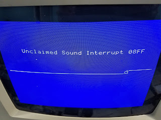
Well, the ROM 03 IIgs came and I left it in a box for many months. Finally, last Father's Day, I opened it and tried to show my kids some games. That's when I discovered that it had a sound problem!
Fast forward to a week ago. An accelerator board and a power supply replacement that I paid for literally 7 months ago finally showed up and I was eager to install it in my ROM 03. But I decided that I really wanted to fix the sound problem before messing with the accelerator.
So I did some basic troubleshooting and this stuff was happening:

My first attempt to fix the problem was to simply de-solder the sound chip and socket it.


I've done this sort of thing several times on arcade PCBs so not only was I familiar with how to do it, but I already had a de-soldering gun along with several 40 pin sockets so I didn't have to wait for any parts to arrive.
Unfortunately, it did not fix my problem.
I wanted to replace the sound chip, but didn't want to destroy a working Apple IIgs. Fortunately, someone was selling a "battery acid destroyed" IIgs motherboard on ebay, so I got it for fairly cheap.
The acid damage was really bad but it looked like the sound chip was still okay, so I desoldered it.

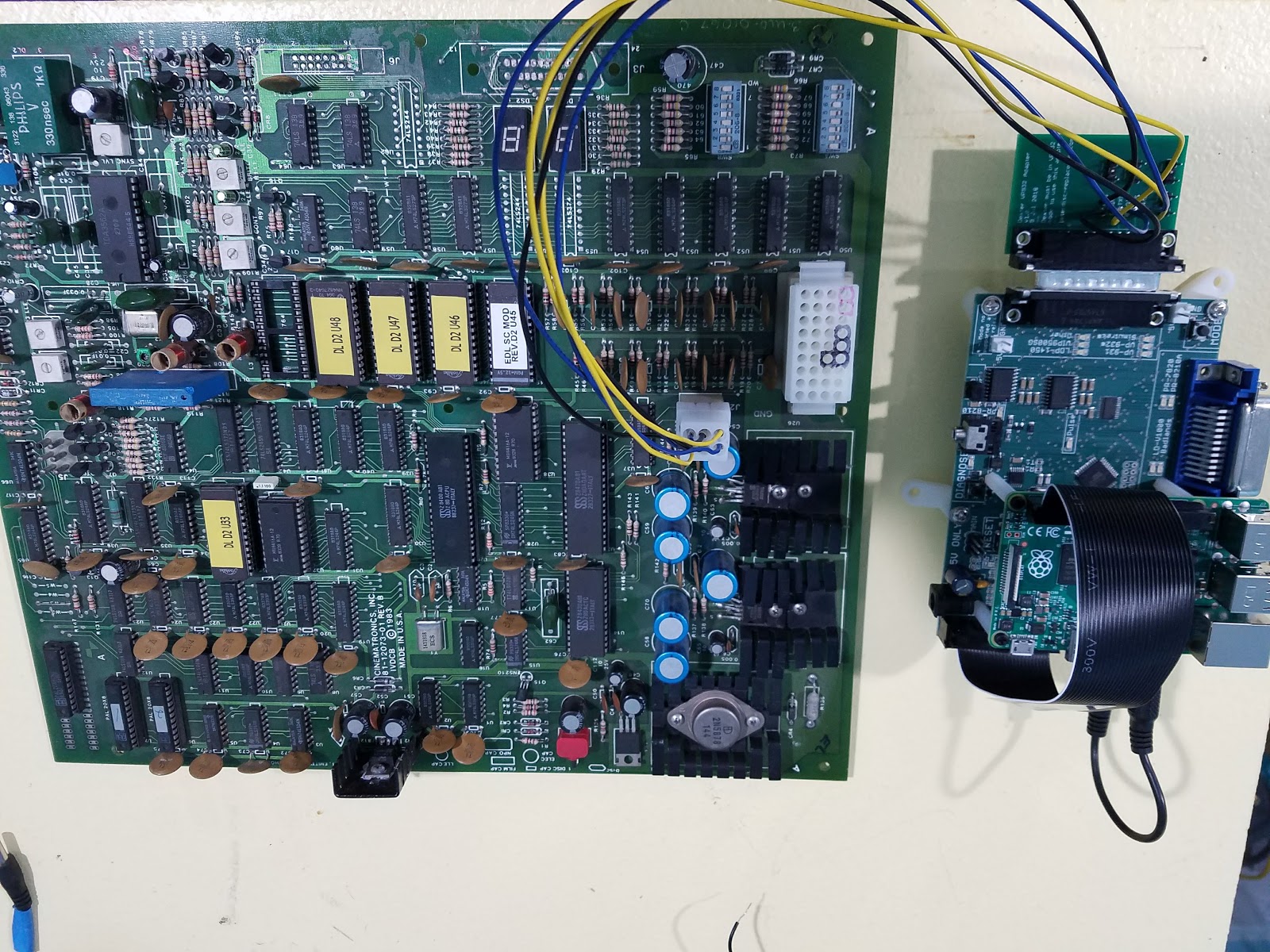
I plugged the replacement sound chip into my ROM 03 IIgs ...


Wow! Despite thinking that replacing the sound chip would likely fix the problem, I was still a bit giddy to see that it actually worked! :)
I fired up a game to test the sound ...

and everything sounds great!
I'm one happy camper.
Now... to install that accelerator board... :)
I still have this original machine and it's a ROM 01 machine which means it may have more game compatibility. Apple also released a ROM 03 version which is newer, has more memory, but may not play every game that the ROM 01 could. I decided to purchase a ROM 03 a year or so ago so that if my siblings ever came and demanded the ROM 01 family machine back, I'd still have a IIgs that I could call my own :)
Well, the ROM 03 IIgs came and I left it in a box for many months. Finally, last Father's Day, I opened it and tried to show my kids some games. That's when I discovered that it had a sound problem!
Fast forward to a week ago. An accelerator board and a power supply replacement that I paid for literally 7 months ago finally showed up and I was eager to install it in my ROM 03. But I decided that I really wanted to fix the sound problem before messing with the accelerator.
So I did some basic troubleshooting and this stuff was happening:


My first attempt to fix the problem was to simply de-solder the sound chip and socket it.


I've done this sort of thing several times on arcade PCBs so not only was I familiar with how to do it, but I already had a de-soldering gun along with several 40 pin sockets so I didn't have to wait for any parts to arrive.
Unfortunately, it did not fix my problem.
I wanted to replace the sound chip, but didn't want to destroy a working Apple IIgs. Fortunately, someone was selling a "battery acid destroyed" IIgs motherboard on ebay, so I got it for fairly cheap.
The acid damage was really bad but it looked like the sound chip was still okay, so I desoldered it.

I plugged the replacement sound chip into my ROM 03 IIgs ...

and fired up the self-test...


I fired up a game to test the sound ...

and everything sounds great!
I'm one happy camper.
Now... to install that accelerator board... :)
Tuesday, October 2, 2018
How to dockerize Intel Quartus 18.01
I've been working with the Domesday Duplicator lately and one of the pieces of hardware that they use is the DE0-Nano board. Domesday documentation focuses on linux tools so I
booted into my Ubuntu and got the DE0-Nano IDE software (called 'Quartus') working. While I was successful, I found it a bit of a pain to figure out which components of the software to download, and would've preferred a pre-built VM or a Docker image. The Quartus license likely does not allow distribution of pre-built Docker images, so I have outlined the steps to create one from scratch here.
The benefits to running this program from a docker container are:
The benefits to running this program from a docker container are:
- The docker image, once created, will likely work on many more platforms than what the native installation option offers.
- Building and running the Docker image is relatively easy.
- Installing and uninstalling is simple and clear.
- Be using some linux flavor (I am on Ubuntu 18.04).
- Install Docker and configure it so that normal users can access it (beyond scope of this blog post).
- Create a file called /etc/udev/rules.d/51-usbblater.rules which has the following contents: (this file is necessary to allow non-root access to the USB device)
SUBSYSTEM=="usb", ATTRS{idVendor}=="09fb", ATTRS{idProduct}=="6001", MODE="0666" - Run "sudo udevadm control --reload-rules" to make the change take effect
- Download Quartus 18.1 Lite for linux, including the Cyclone 4 package. The filenames I downloaded are called QuartusLiteSetup-18.1.0.625-linux.run and cyclone-18.1.0.625.qdz .
- Create a new subdirectory and copy QuartusLiteSetup-18.1.0.625-linux.run and cyclone-18.1.0.625.qdz into it.
- Inside this subdirectory, create a file called Dockerfile and paste this into it:
# ubuntu 18.04 is officially supported by this version of quartus
# libpng12 included in 16.04 but not in 18.04, so we use 16.04 for convenience
FROM ubuntu:16.04
ENV DEBIAN_FRONTEND noninteractive
ARG QUARTUS=QuartusLiteSetup-18.1.0.625-linux.run
ARG CYCLONE=cyclone-18.1.0.625.qdz
COPY $QUARTUS /$QUARTUS
COPY $CYCLONE /$CYCLONE
RUN apt-get update && \
apt-get -y -qq install apt-utils sudo && \
apt-get -y -qq install locales && locale-gen en_US.UTF-8 && \
apt-get -y -qq install software-properties-common \
libglib2.0-0:amd64 \
libfreetype6:amd64 \
libsm6:amd64 \
libxrender1:amd64 \
libfontconfig1:amd64 \
libxext6:amd64 \
libpng12-0:amd64 \
xterm:amd64 && \
chmod 755 /$QUARTUS
# create a normal user so we're not running as root
RUN export uid=1000 gid=1000 && \
mkdir -p /home/developer && \
echo "developer:x:${uid}:${gid}:Developer,,,:/home/developer:/bin/bash" >> /etc/passwd && \
echo "developer:x:${uid}:" >> /etc/group && \
echo "developer ALL=(ALL) NOPASSWD: ALL" > /etc/sudoers.d/developer && \
chmod 0440 /etc/sudoers.d/developer && \
chown ${uid}:${gid} -R /home/developer
# switch to user so it installs from the user's context
USER developer
ENV HOME /home/developer
# install quartus as the user (not root)
RUN /$QUARTUS --mode unattended --unattendedmodeui none --installdir /home/developer/altera_lite --accept_eula 1 && \
sudo rm -f /$QUARTUS && \
sudo rm -f /$CYCLONE
# run from xterm to capture any stdio logging (not sure there is any, but can't hurt)
CMD xterm -e "/home/developer/altera_lite/quartus/bin/quartus --64bit" - From within this subdirectory (which contains the three files), run this command:
"docker build -t quartus18 ." - It will take ~15 mins depending on the speed of your system. When it finishes, your Docker image will be generated and will be called "quartus18". You may now optionally delete the sub-directory that you created to generate the docker image.
- Plug in your DE0-Nano to a USB port. Be sure to unplug any other sources of power (for example, the FX3 board, if you have a DdD 'stack' ) or you will get unexplained errors.
- From a desktop session, run the following command:
docker run --rm -v /sys:/sys:ro -v $HOME:/shared -v /tmp/.X11-unix:/tmp/.X11-unix -e DISPLAY -e "QT_X11_NO_MITSHM=1" --privileged -v /dev/bus/usb:/dev/bus/usb quartus18 - If all goes well, the Quartus app will launch inside of the container. Your host's home folder will be accessible as /shared in the root. Follow the instructions from DdD site. You may also find this youtube video helpful.
- When you exit the program, the container will automatically delete/uninstall itself.
Monday, October 1, 2018
How to dockerize Cypress FX3 Linux USB programmer
I've been working with the Domesday Duplicator lately and one of the pieces of hardware that they use is the FX3 board from Cypress. Domesday documentation focuses on linux tools so I booted into my Ubuntu and got the FX3 USB programmer working. It wasn't that easy, though. For example, I had to modify the source code to fix a build error. Installation seems to be one-way, meaning there is no uninstall (which seems somewhat rude). It would've been cool to run this in a VM so that when I was done, I could just shut the VM down. That is kind of a huge pain, though. A better option is Docker! The problem is, the software's license likely prohibits it being distributed as a docker container, so one must create one from scratch. Fortunately, after some experimenting, I got it all working.
The benefits to running this program from a docker container are:
Neat, eh?
The benefits to running this program from a docker container are:
- The docker image, once created, will likely work on many more platforms than what the native installation option offers.
- You don't have to install all of the qt4 dev packages on your native OS.
- Uninstalling is simple and clear. (no weird files leftover in weird places)
- Be using some linux flavor (I am on Ubuntu 18.04).
- Install Docker and configure it so that normal users can access it (beyond scope of this blog post).
- Create a file called /etc/udev/rules.d/88-cyusb.rules which has the following contents: (this file is necessary to get flash programming mode to work)
# Cypress USB driver for FX2 and FX3 (C) Cypress Semiconductor Corporation / ATR-LABS
# Rules written by V. Radhakrishnan ( rk@atr-labs.com )
# Cypress USB vendor ID = 0x04b4
KERNEL=="*", SUBSYSTEM=="usb", ENV{DEVTYPE}=="usb_device", ACTION=="add", ATTR{idVendor}=="04b4", MODE="666", TAG="cyusb_dev", RUN+="/usr/local/bin/cy_renumerate.sh A"
KERNEL=="*", SUBSYSTEM=="usb", ENV{DEVTYPE}=="usb_device", ACTION=="remove", TAG=="cyusb_dev", RUN+="/usr/local/bin/cy_renumerate.sh R" - Run "sudo udevadm control --reload-rules" to make the change take effect
- Create a script called /usr/local/bin/cy_renumerate.sh that contains this:
#!/bin/bash
pid=`pidof cyusb_linux`
if [ "$pid" ]; then
kill -s SIGUSR1 $pid
fi - Type "chmod a+x /usr/local/bin/cy_renumerate.sh" so the script can be executed
- Download the Cypress FX3 linux SDK (try here or search for "cypress fx3 linux sdk")
- Extract the archive and locate the file called cyusb_linux_1.0.5.tar.gz .
- Create a new subdirectory and copy cyusb_linux_1.0.5.tar.gz into it.
- Inside this subdirectory, create a file called Dockerfile and paste this into it:
# this is known to work on 18.04, may not work on later versions
FROM ubuntu:18.04
ARG DEBIAN_FRONTEND=noninteractive
ARG CYUSB=cyusb_linux_1.0.5.tar.gz
COPY $CYUSB /$CYUSB
RUN apt-get update && \
apt-get -y -qq install apt-utils && \
apt-get -y -qq install sudo qt4-default \
less make g++ dialog libusb-1.0-0-dev \
xterm
RUN export uid=1000 gid=1000 && \
mkdir -p /home/developer && \
echo "developer:x:${uid}:${gid}:Developer,,,:/home/developer:/bin/bash" >> /etc/passwd && \
echo "developer:x:${uid}:" >> /etc/group && \
echo "developer ALL=(ALL) NOPASSWD: ALL" > /etc/sudoers.d/developer && \
chmod 0440 /etc/sudoers.d/developer && \
chown ${uid}:${gid} -R /home/developer
# switch to user so it installs from the user's context
USER developer
ENV HOME /home/developer
# needed so cypress app can program itself to go into flash mode
ENV CYUSB_ROOT /home/developer/cyusb_linux_1.0.5
# build/install
RUN sudo chmod a+r /$CYUSB && \
tar xvfz /$CYUSB -C /home/developer && \
sudo rm -f /$CYUSB && \
cd $HOME && \
cd cyusb* && \
make && \
sed -i 's/errno/_errno/g' gui_src/main.cpp && \
sudo ./install.sh
# put /usr/local/lib in the lib search path so running 'cyusb_linux' from anywhere works
RUN sudo sh -c "echo '/usr/local/lib' >> /etc/ld.so.conf.d/cyusb.conf" && \
sudo ldconfig
# launches in xterm so we can see log messages
CMD xterm -e "cyusb_linux" - From within this subdirectory (which contains the .tar.gz file and Dockerfile), run this command:
"docker build -t cyusb ." - It will take ~5 mins depending on the speed of your system. When it finishes, your Docker image will be generatedand will be called "cyusb".
- Plug in your FX3 to a USB port.
- Make sure that the FX3 image that you want to program to the FX3 is stored somewhere under your home directory.
- Run the following command:
docker run --rm \
-v $HOME:/shared:ro \
-v /tmp/.X11-unix:/tmp/.X11-unix \
-e DISPLAY \
-e "QT_X11_NO_MITSHM=1" \
--privileged \
-v /dev/bus/usb:/dev/bus/usb \
cyusb - If all goes well, the cyusb app will launch inside of the container. Your host's home folder will be accessible as /shared in the root. Follow the instructions from DdD to complete the programming.
- When you exit the program, the container will automatically delete/uninstall itself.
Neat, eh?
Docker tips
I've had the need to learn more about Docker lately and had some trouble getting stuff working. Here are some helpful links that I used to solve problems, put here so I can refer to them later (or so anyone else can benefit from them).
To docker-ize UI applications:
http://wiki.ros.org/docker/Tutorials/GUI
https://blog.docker.com/2013/07/docker-desktop-your-desktop-over-ssh-running-inside-of-a-docker-container/
http://fabiorehm.com/blog/2014/09/11/running-gui-apps-with-docker/
To expose USB devices to docker containers:
https://stackoverflow.com/questions/24225647/docker-a-way-to-give-access-to-a-host-usb-or-serial-device
Thursday, August 30, 2018
Had to make a new VP932 adapter
Well, my first attempt at a VP932 adapter revealed some problems so I've ordered a second revision.


This one has a MAX232A chip on the board. I wasn't able to find a solution without converting to RS232 voltages, even though the AVR on the Dexter board can accept TTL serial natively. This is partially due to the safeguards I put in place for VP931 (Firefox) support.
Saturday, July 21, 2018
Euro DL PCB arrived today!
Thanks to Matteo Marioni, I now have a Euro Dragon's Lair PCB on loan for Dexter development. The molex connector that I soldered up for the Dexter add-on board seems to fit! Phew!
I just happened to have the 36-pin connector type (which isn't available to buy anymore!) so my next step is to create a test bench wiring harness and then hook up a logic analyzer to sniff the serial I/O. This is exciting progress!
Tuesday, July 17, 2018
Star Rider arcade game in action (using Dexter)
Monday, July 16, 2018
Philips VP932 ptototype add-on board for Dexter now ready for testing

Thursday, July 12, 2018
Philips 22VP932 connector cable made!
I got my feet weight crimping molex pins. I made a prototype connector for the Philips 22VP932 that Dexter will be replacing.


Friday, July 6, 2018
Gigabit Fiber: How to replace Century Link provided router with your own
So I've had Century Link gigabit fiber for about a year now and have been leasing their "zyxel C2100Z" supplied router the entire time. I think it's $10/month. I've basically paid them $120 just to borrow their equipment for the past year.
It just so happens that I previously already owned an EdgeRouter Lite (back from when I used to be on Comcast). This is a highly-rated router which is also fairly inexpensive which is a win in my book. The downside is it can be a little hard to configure at first.
The ZyXel C2100Z seems to perform well, but is kind of annoying. It tends to forget port forwarding features occasionally. Plus, I don't like paying to lease it when I already have a router which I suspected I could get working.
So today was the day. I broke down and decided to get my EdgeRouter Lite working with Century Link fiber.
I pulled out a LOT of hair (figuratively) but was eventually successful so I am documenting my journey.
If it didn't work, double check that you are indeed using the VLAN id of 201 as shown earlier. If you don't use this, the Century Link equipment will completely ignore your router's attempts to authenticate which is very frustrating.
It just so happens that I previously already owned an EdgeRouter Lite (back from when I used to be on Comcast). This is a highly-rated router which is also fairly inexpensive which is a win in my book. The downside is it can be a little hard to configure at first.
The ZyXel C2100Z seems to perform well, but is kind of annoying. It tends to forget port forwarding features occasionally. Plus, I don't like paying to lease it when I already have a router which I suspected I could get working.
So today was the day. I broke down and decided to get my EdgeRouter Lite working with Century Link fiber.
I pulled out a LOT of hair (figuratively) but was eventually successful so I am documenting my journey.
- Call Century Link to get your PPP username/password. Phone number is 1-800-247-7285. If you don't know which options to choose, they have one about 'internet not working' and 'getting help with wireless password'. I chose this one and got on the phone with someone who could help me. I just asked him for my PPP username/password and explained that I wanted to use my own router.
- Upgrade firmware on EdgeRouter Lite to ensure that PPPoE is in their web UI (no one likes messing with config files!). The latest version at the time of this writing is v1.10.5
- Backup your existing config (if you have one) using System->"Back Up Config" from the web UI. You can restore it later (and modify it) once you have gone through the rest of these instructions successfully.
- Restore factory settings (for the purpose of this tutorial).
- Plug your LAN into eth0 of the EdgeRouter. Change your IP address to 192.168.1.x (not 1) and connect to 192.168.1.1 (after router reboots, it takes a few minutes)
- Log in using ubnt/ubnt for username/password.
- If the 'basic setup' wizard doesn't launch, start it (I think it auto launches).
- Setup eth0 as your gateway, and eth1 as your LAN (via separate gigabit switch). Ignore eth2 for performance reasons. Ignore PPPoE options for now.
- Save settings and reboot as prompted.
- Move your LAN cable from eth0 to eth1 and plug your centurylink WAN cable (ethernet, the one that plugs into the zyxel's WAN port) into eth0.
- Log back into the dashboard after the router reboots (via 192.168.1.1)
- From the dashboard, click "Add new interface". Choose VLAN. For the VLAN id, choose 201. (Century Link uses 201, this is the part that got me stumped!) For interface, choose eth0. Leave MTU at 1500. Leave address as "no address".
- From the dashboard, click "Add new interface". Choose PPPoE. For the ID, choose 0. For interface, you should have a new interface called eth0.201; choose that. For account name, put in your century link PPP user, for password put in your century link PPP password, for MTU put in 1492.
- If all goes well, your dashboard should now show your new PPPoE as 'connected'. You can now configure your router as you choose or restore your previous config and try to apply these steps to it.
Using "Config Tree" from the web UI:
- System->Offload->PPPoE (this may be blank, be sure to set it to 'enabled' or your performance will be under 100 mbit instead of near 1000 mbit).
- Make sure your NAT masquerade outbound interface is pppoe
If it didn't work, double check that you are indeed using the VLAN id of 201 as shown earlier. If you don't use this, the Century Link equipment will completely ignore your router's attempts to authenticate which is very frustrating.
Good luck!
Alternate reading: https://nickmooney.com/centurylink-fiber-bypass-modem/
Sunday, June 3, 2018
Star Rider NTSC board cap kit
The Star Rider NTSC board doesn't seem that great. I thought that perhaps I could get some better image quality out of it if I replaced the capacitors. I do so in this video. Frankly, I'm not sure if it's worth it, but I am going to document the parts that I used for posterity just in case.
| Schematic symbol | Manufacturer | Product part | Description |
| C001,C205,C207,C208 | Nichicon | UKL1V100KDDANA | 10uF, 25V radial, 'low leak' (replaces two axials on original board) |
| C102, C405 | Nichicon | UKL1E470KEDANA | 47uF, 25V |
| C209,C800,C801 | Nichicon | UKL1C471KPD | 470uF, 16V |
| C701, C601 | ? | ? | 1uF, 50V; I missed these and didn't replace these, just adding it here for future reference |
Wednesday, May 30, 2018
Punch-Out 'no burn-in' video showing my new mod in action
In a recent blog post, I detailed changes I made to the Punch-Out ROM to reduce risk of getting 'burn-in' on my CRT monitors. I felt like my explanation was a bit confusing so I went ahead and filmed a video showing what the mod actually does.
Monday, May 28, 2018
Punch Out Arcade Free Play Enhancement
("Too Long Didn't Read", skip to the end!)
So I recently acquired a Punch-Out arcade game (one of the ones I remember playing as a kid, could never defeat Bald Bull!). It came with a helpful freeplay mod installed (which I am assuming came from here ) which is a really nice improvement from the stock Nintendo freeplay mode. The stock freeplay mode basically coins up the game on power-up and sits there waiting for a button press, which puts the game's CRT monitors at risk of burn-in. The freeplay mod I linked is a big improvement but it still has some room for improvement. Specifically, when 'coining up' by pressing 'uppercut', the player is taken to a screen where they must manually press the left punch button in order to start the game. As far as I can tell, this screen never goes away. Why is this bad? Well, I have kids and I have a day job. If the kids power on my Punch-Out while I'm gone and leave it in this aforementioned state, my CRT is at risk of burn-in. Believe me, I do _NOT_ want to find a replacement for these CRTs! I've got much better things to do with my time!
So I decided to see if I could improve the freeplay mod I mentioned before to never leave the screen stuck waiting for a button press.
I used MAME's source code to get memory map and I/O map of the game, MAME's excellent built-in debugger to set breakpoints and watchpoints, and my trusty copy of IDA (Interactive Disassembler) to make understanding the code easier. I also compared the aforementioned freeplay mod with the unmodified ROM to take a shortcut to understanding where the game looks for coin insertions.
Here is what the previous mod changes:
ROM:039A in a, (3) ; query dip switches
ROM:039C and 0Fh ; isolate free play
ROM:039E cp 0Fh ; are we in free play mode?
ROM:03A0 jr nz, NotFreePlay ; branch if not in free play mode
The mod changes 39C to AND with 0 instead of 0Fh and to compare with 1 instead of comparing with 0Fh. This has the result of always taking the branch of 3A0 which pops us into the normal attract mode on power-up instead of Nintendo's crappy original freeplay behavior.
Next mod is at 61d:
ROM:061D in a, (1) ; query joystick and coins
ROM:061F ld e, a
ROM:0620 ld b, 80h ; isolate coin1
ROM:0622 call ActIfCoinInserted
ROM:0625 ld l, 0D6h
ROM:0627 ld a, e
ROM:0628 ld b, 40h ; '@' ; isolate coin2
ROM:062A call ActIfCoinInserted
the mod moves this code to an unused section of the ROM at $2AC0 and adds a check to see if the upper-cut button (aka button 3) is pressed. If it is, it does some other simple checks and eventually ensures that 1 credit is now available which normally puts the game into the mode where it prompts the player to press left punch to start a new game.
I had no idea where this loop took place that repeatedly polled the state of the left punch button. Fortunately, MAME's built-in debugger is quite powerful and allows setting of I/O watch points. I referred to MAME's source code for Punch-Out and discovered that the buttons are read by reading I/O port 0. So I simply told MAME to break any time something somewhere in the code read this port.
In addition to MAME breaking at the modified code to check to see if the uppercut button was being pressed, it rewarded me by breaking here:
ROM:12BA CheckLeftPunchNewGame: ; CODE XREF: ROM:12DA↓j
ROM:12BA in a, (0)
ROM:12BC and 1 ; check to see if button 1 is pressed
ROM:12BE jr nz, loc_12B5 ; branch if it's pressed
ROM:12C0
ROM:12C0 LeftNotPressed: ; CODE XREF: ROM:12F0↓j
ROM:12C0 call sub_2937
ROM:12C3 jr loc_1289
This was clearly the code I was looking for to see if left punch was getting pressed.
The only danger was that I didn't know if this code only got called after a coin was inserted and while waiting to start a new game or if it was a generic 'read the button' routine and was used during the game itself. If the former, I could just change the behavior of the branch to always assume that the button was being pressed. If the latter, I would have to dig deeper to avoid altering the behavior of the gameplay itself.
I disabled the breakpoint, then started a game. As soon as Glass Joe appeared, I re-enabled the breakpoint at $12BA and to my delight, the breakpoint was not getting hit. This meant that the code was only used when waiting for a new game. Woohoo!
Now I just had to find the code that checked to see if the player wanted to do a 'rematch' after losing the game. I knew that I had to change the behavior from the way the original game worked to prevent potential burn-in, so I had to make a decision about whether to always start a new game if a player 'coins up' during the fast timer, or always do a rematch if the player 'coins up' during the fast timer. I decided that if the player 'coins up' after losing the game, this means that they always want to do a rematch (never a new game). If the player wants to do a new game, they'll just have to let the fast timer expire.
I had noticed some other code near $12BA which also read from I/O port 0 but checked for button 2 (aka right punch). The code was here:
ROM:12E6 CheckBothButtonsGameOverCreditIsNonZero:
ROM:12E6 ; CODE XREF: ROM:12E2↑j
ROM:12E6 in a, (0)
ROM:12E8 and 4
ROM:12EA jr nz, loc_12B5 ; branch if right is pressed
ROM:12EC in a, (0)
ROM:12EE and 1
ROM:12F0 jr z, LeftNotPressed
So I set a breakpoint at $12E6, then destroyed Glass Joe and allowed Piston Hurricane to defeat me.
After my game was over, I saw the 'fast timer' urging me to insert a coin. I hit 'uppercut' to credit up, and was gratified to have the debugger break at $12E6. Woohoo!
From this point, future modifications were easy:
I simply had to change the "jr nz, 12b5" at $12BE to "jr 12b5" (always jump instead of jump if non-zero) and do a similar change at $12EA from "jr nz, 12b5" to "jr 12b5".
This mod was fairly easy for me to perform but I stood on the shoulders of giants who did all of the hard work. The tools that made it easy:
- MAME source code that had the I/O ports and memory map
- MAME debugger (super nice for a free project)
- The pre-existing freeplay mod that allowed me to take some major shortcuts
TOO LONG, DIDN'T READ:
- Apply the Punch-Out freeplay mod from here .
- Using a hex editor, make these additional changes inside of the EPROM at 8L (MAME calls it chp1-c.8l),
change $12BE from 20 F5 to 18 F5
and
change $12EA from 20 C9 to 18 C9
Hopefully this makes it so you never have to worry about CRT burn-in even if your kids are playing your game while you are gone.
Friday, May 11, 2018
Dexter Audio Quality Update
Via Dexter Manager, people can now enjoy better quality audio when using Dexter!
Saturday, May 5, 2018
How much power does Star Rider actually use?
I've been looking into making a replacement power supply PCB for Star Rider since my original one is currently not working. I've been running Star Rider off an ATX power supply for years and it seems to work fine. But newer ATX power supplies are starting to really get cheap on the -12 V current. I tried a brand new one and it didn't have enough -12V juice to run the game properly. So I decided to do some tests and see just how many amps the -12V (and 12V) rails need to provide to run the game.

Not pictured is the 5V power supply that I rigged up. The current on the 5V power supply I wasn't able to accurately measure, but it seems to need 6A, maybe even 10A, to be stable, so that is by far the most demanding of the power requirements.
Conclusion: both the 12V and -12V supplies seem to need around 0.51A so an ATX power supply with 0.8A on the -12V rail should do the job; the newer one that I tried only put out 0.3A which is why it failed miserably.
Hopefully they still make ATX power supplies with 0.8A on the -12V line. The one that I am successfully using was made for a Pentium 4 so it's pretty old these days.
Thursday, April 5, 2018
Yet another Star Rider repair
Would you use ice to find a troublesome part on a large board with a lot of generic TTL ICs? Wise people wouldn't. I may not be a wise person.
Monday, March 26, 2018
Isolation transformer and AC power
I found this old conversation with Mitch Schleiss about AC power and isolation transformers. Posting it here so it gets preserved.
A lot of the old monitors have what we call a "hot chassis" meaning the metal frame portion is directly connected to 110vac. If you were to touch it and ground yourself, meaning the ground plug on an outlet and/or a metal pipe in your house, you would be shocked by 110ac. If you were to touch the metal frame to a ground, you would probably blow out a transistor or diode. You need an isolation transformer which just has the same amount of windings on both the primary side and the secondary side to give you that 110ac in and 110ac out. Seems like a dumb transformer but what it does is that there is no direct connection between the house wiring and the monitor: "isolated" They are harder to come by now a days but is really needed for safety and component protection. I have worked on monitors without it but you need to really understand what is going on!
http://teaganm.cademo.com/images/other/randyfromm/isoxfmr.htm
The monitor is not connected to the ground at all. The problem with the term ground is that it means too many things. There is the power supply ground-referenced to the 5 volts. There is the FG or Frame Ground or sometimes called Floating Ground which usually means the Ground to the round plug on the ac outlet which should connect to the actual earth ground. and some others too.
In the days of arcade games, you would find switching power supplies with the ground and the FG connected together. This is wrong and could cause all kinds of issues beyond safety like ground loops and audio humm. The 2 spades on an ac plug are actually a hot and a neutral (which is actually the same as earth ground) but most people who wire up your house are morons and dont care which one goes where as it is just AC to them.
The ground on an ac outlet is really there for safety. It is made so if something goes wrong, it is supposed to bleed off the power to ground instead of THROUGH you. More of a UL safety law here in the states. That is why you see things like laptop power supplies with no ground. THey are completely covered in plastic and thus you can not touch anything that is HOT even if it malfunctions.
My added notes:
Looks like you really can touch either side of the AC output of the isolation transformer and not get shocked!

Yes, I am touching the metal here. Yes, it is powering the light bulb. Yes, I am not getting shocked.
Touching both sides at the same time would likely shock one. I am not going to attempt it.
Another link on the subject: http://www.powerinspired.com/isolation-transformer-need-know/
The frame of my G07 is not connected to either AC input wire. Therefore, I believe it should indeed be connected to earth.
Sunday, March 25, 2018
Dexter now support ALG multi-ROM
If you've enjoyed the ability for Merlin-Dx and Dexter to let you switch between three games (Dragon's Lair, Space Ace, and Dragon's Lair 2) then you may be excited about this new free update to Dexter which will allow Shaun Wood's ALG multi-ROM to tell Dexter which laserdisc image to load!
Saturday, March 24, 2018
Exploring a 110V AC outlet solid state relay
ne
Needed for a future project, I had a hard time knowing how these things are supposed to work. Most youtube videos I watched assumed that the wiring was obvious and didn't explain it. I decided to find out for myself.
Tuesday, January 2, 2018
I think I finally understand how Star Rider's manchester/biphase decoder works
I've been scared to dig into one of the Star Rider schematics, the one with the "biphase" decoder on it. This circuit is how it grabs the picture number from the laserdisc video signal, and how it also decodes the other biphase (aka manchester) data that exists on the disc.
I've put verbose comments on the schematic page so that I never forget what I've learned. I hope someone finds it interesting as this represents somewhat of a victory for me :)
Since the jpg is large, I've hosted it on my wiki. Click here here to view.
I've put verbose comments on the schematic page so that I never forget what I've learned. I hope someone finds it interesting as this represents somewhat of a victory for me :)
Subscribe to:
Posts (Atom)