Ever written something like this?
int count = 2;
int count2 = 4;
int count3 = 6;
Watch this stunningly insightful video (sarcasm) to find out why this is a Bad Idea.
Showing posts with label avr. Show all posts
Showing posts with label avr. Show all posts
Sunday, February 7, 2016

Monday, March 23, 2015
How many microseconds is one CPU cycle?
I had to figure this out (again), so I am writing this down for future reference.
(1*10^6 microseconds/1second)(1second/CpuHz)1 cycle = ? microseconds
For example, if my CPU is 18.432MHz, then the formula would be:
(1000000/18432000) = microseconds of 1 CPU cycle, which is 0.054 uS
(1*10^6 microseconds/1second)(1second/CpuHz)1 cycle = ? microseconds
For example, if my CPU is 18.432MHz, then the formula would be:
(1000000/18432000) = microseconds of 1 CPU cycle, which is 0.054 uS
Saturday, August 2, 2014
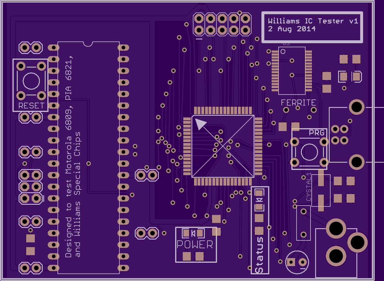
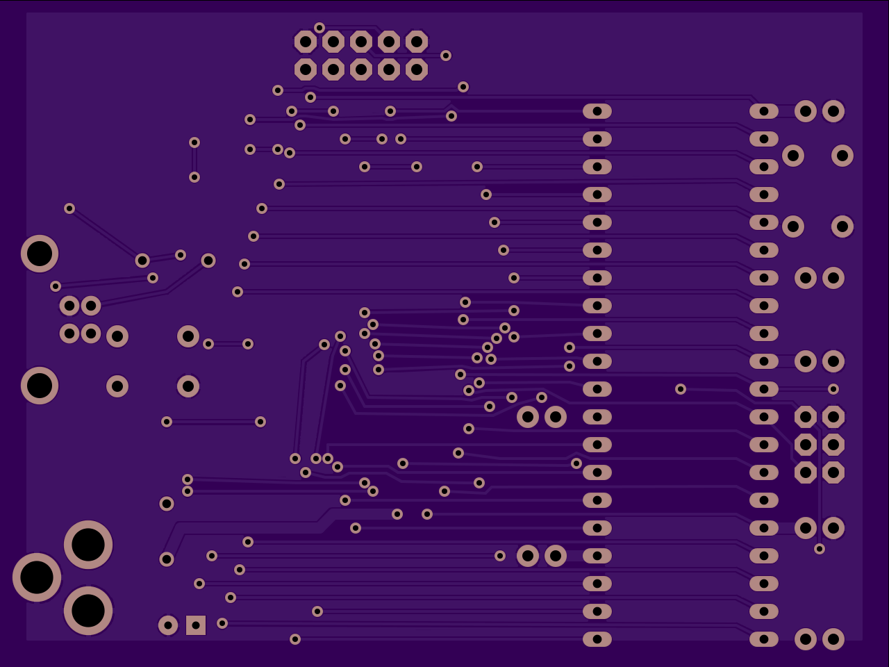
Making a new PCB to test/validate Williams ICs
Star Rider testing has got me so frustrated with suspicions of faulty hardware that I am making a little board to test the big ICs that Star Rider uses: the Motorola 6809E CPU, the Motorola PIA 6821, and the Williams Special Chips.
Tuesday, July 1, 2014
First Dexter rev3 prototype almost finished
Well, I stayed up way too late working on this, but I've mostly finished soldering! I also learned a few things about skillet temperature, mainly, that it is possible for it to be too hot! Hahaha. I burned the PCB pretty badly but INCREDIBLY, so far everything is still working!
I put solder paste on half of the board, then got scared of accidentally nudging an IC out of position and decided to solder the ICs on first before continuing with the rest of the easier parts.

The IC soldering went incredibly well. I only had about 3 solder bridges. The middle of the board has started to turn brown at this point but I wasn't worried. I knew I just had to use less heat on the hot plate the second go around.

The second go around using the hot plate was pretty scary as the board started sizzling, smoking, and turning very dark brown (as you can see). I thought "OH NO, I've ruined the board and all my work is for naught!!" But I decided to solder on a few components to see how bad the damage was and WOW, everything is working so far. Both microcontrollers (AVR 644p and 328p) work, crystals work, and the LEDs (which look horrible after the burn) work too. I don't want to get overoptimistic here, but I think this board might be saved! And don't worry, I will be keeping this one for myself so no one has to worry about getting a burnt prototype board :)


Friday, February 28, 2014
Soldering VBI Injector board v3
I had made a version 3 of the VBI injector board some time ago, and had even made a first attempt at soldering it together. However, the AVR did not work and I already suspected that it was bad. I finally ordered a new one. It became time to solder it on and I decided to use the "hot plate/skillet" method.
This method is to basically apply some solder paste on the PCB, put the surface mount components on the solder paste, and then heat the entire bottom of the board on a skillet. Melting point of the solder paste is between 425-450F (I forget the C conversion).
Unfortunately, as I had already soldered on some (previously de-soldered) pin headers, the PCB could not get good contact with the skillet. I was hoping that by heating up the pins that the board would slide down once the solder on the pins heated up, and as you can see in the video, it does slide down, but not quite enough.
NOTE : almost all of these components have been desoldered from a previous board which is why they look charred. Only the AVR is new.
So the right side of the board gets hot enough but the left side does not. This means that half of the AVR pins are done.
I decided to use my newly acquired hot air gun to finish the job. As you can see, it worked quite nicely. I was able to finish the 10k resistor, the rest of the AVR, and the MUX IC.
This method is to basically apply some solder paste on the PCB, put the surface mount components on the solder paste, and then heat the entire bottom of the board on a skillet. Melting point of the solder paste is between 425-450F (I forget the C conversion).
Unfortunately, as I had already soldered on some (previously de-soldered) pin headers, the PCB could not get good contact with the skillet. I was hoping that by heating up the pins that the board would slide down once the solder on the pins heated up, and as you can see in the video, it does slide down, but not quite enough.
NOTE : almost all of these components have been desoldered from a previous board which is why they look charred. Only the AVR is new.
So the right side of the board gets hot enough but the left side does not. This means that half of the AVR pins are done.
I decided to use my newly acquired hot air gun to finish the job. As you can see, it worked quite nicely. I was able to finish the 10k resistor, the rest of the AVR, and the MUX IC.
Wednesday, June 26, 2013
VBI Injection v2: Soldering on SMT version of ATMega 328p
A new PCB arrived today. This is the second attempt at VBI injection which uses a video multiplexer instead of an op-amp. I soldered on the hardest component first.
Step one was just to get solder on all the pads, even if the pins are connected when they are not supposed to be. Here you can see I schlopped a bunch of solder on and joined them all.

Step two was to use the solder wick to remove the connections. The finished soldering job looks pretty pro if I do say so myself :)

Tomorrow, I hope to solder on the rest of the components.
I have to say, soldering on this ATMega 328p was a lot easier than I thought it was going to be. The hardest part is getting the pins lined up to the pads before beginning. I also did make the pads extra long to make my job easier.
Thursday, March 17, 2011
New toys


This little board is so I can use that STK600-DIP board with the ATMega328P.


Whoa.. it comes with an AVR chip in the socket! I was not expecting that. And I have no idea which chip this is :) ATMega32L-8PU? huh? I hope it's awesome :)

Wednesday, March 9, 2011
Assembly language routine written!
As I said yesterday, I decided that I needed to re-write my code in AVR assembly language in order to make it fast enough to be able to reliably detect the 4 microsecond bit cells send from the Apple 5.25" disk drive.
I now have ported both the bit detector function and the interrupt service routine (ISR) to assembly language. The ISR was the one that I was the most keen on optimizing because the C compiler added a bunch of wasteful stack pushes/pops that I didn't need, but I also benefited from optimizing the main loop also because I was able to move a global variable from memory into a register which saved a few cycles.. and when talking about microseconds at 14.7 MHz, a few cycles are worth a lot!
I am excited to test out my new routine on real hardware.
Here is the ISR routine below. As you can see, it's pretty short. It gets activated when a read pulse is received from the 5.25" disk drive.
I now have ported both the bit detector function and the interrupt service routine (ISR) to assembly language. The ISR was the one that I was the most keen on optimizing because the C compiler added a bunch of wasteful stack pushes/pops that I didn't need, but I also benefited from optimizing the main loop also because I was able to move a global variable from memory into a register which saved a few cycles.. and when talking about microseconds at 14.7 MHz, a few cycles are worth a lot!
I am excited to test out my new routine on real hardware.
Here is the ISR routine below. As you can see, it's pretty short. It gets activated when a read pulse is received from the 5.25" disk drive.
// this interrupt is triggered when a pulse (connected to INT6 pin) starts (active low)
.global INT6_vect
INT6_vect:
 in sreg_save, _SFR_IO_ADDR(SREG) ; preserve flags

 ; When we store this cycle value to the timer, it will be at most 1 cycle off so it is pretty accurate
 ; I got this value by counting cycles in the simulator/debugger.
 ; I want the timer to be relative to the start of the pulse so it's easier to visualize in my head.
 ; The timer will not overflow within the time that it is useful to us.
 ldi u8Timer, 12
 out _SFR_IO_ADDR(TCNT0), u8Timer

 clr bPulseOccurred ; this register should already be 0 in every case but I want to be safe and this only uses 1 cycle
 inc bPulseOccurred ; let main loop know that a pulse started

 ; we need to wait for the pulse to end or else this ISR will get triggered again immediately
wait_pulse_end:
 sbis _SFR_IO_ADDR(PINE), 6
 rjmp wait_pulse_end

 out _SFR_IO_ADDR(SREG), sreg_save ; restore flags
 reti
Monday, March 7, 2011
Setting up my AVR has been a real pain
So recently (within the last month), I decided that I needed to learn about micro-controllers (basically cheap mini CPUs) so I could move some of My Cool Projects forward. A friend recommended the Atmel STK600 as a good starter kit, so I got one. The good news is that the STK600 is pretty awesome, the bad news is that the documentation for it is abysmal. So I've been maintaining my own "getting started" guide to help anyone else who may want to tread these waters.
You can find my guide here.
You can find my guide here.
Subscribe to:
Posts (Atom)