Saturday, November 20, 2021

My Dragon's Lair 2's RAM wasn't working. Here's how I [finally] discovered the problem!

I've had a DL2 boardset for a few years but have never tried to power it on.  I also did not have a harness for it.  Well, recently I decided to try to get it running.  After making a power harness and a speaker harness, and burning a v3.19 EPROM, it was time to give it a shot!

Well, after powering it on, nothing happened.  Three LEDs lit up, but there were no beeps and no I/O on the serial port that I could see.  Ugh.  After scanning some forums, I determined that the most common problem with getting DL2 working was the null modem adapter (it is non-standard).  I studied the schematics and owners manual and determined that this was likely not my problem.

As I was basically blind, I decided to do what anyone would do who is a glutton for punishment: to sniff the pins of the CPU to see where it was getting stuck (or if it was even working).

The CPU type is 8088 which I was very unfamiliar with.  I mean, I knew the assembly language command set quite well, but knowing what the actual pins on the CPU did, I was in the dark.

I pulled up the datasheet and was kinda mortified about how convoluted this CPU's design is.  Unlike other 8-bit CPUs of the era (Z80, 6809), this 8088 CPU can address 1M of addressing space (instead of 64k) which you'd think would be a good thing.  But unfortunately, to cram this functionality into 40 pins, they share the address lines with the data bus and some status bits.  This makes decoding the CPU quite a challenge and often requires a separate IC near the CPU to present a normal address and data bus for the rest of the system.  I am frankly a little shocked that intel won the CPU wars of the 80's as a result of this.

In order to make parsing a logic analyzer capture of the CPU more convenient, I needed to sniff a pin of said separate IC to make my life easier.  This pin is called the ALE (hehe) pin, or Address Latch Enabled.  Studying a hard-to-read schematic of the DL2 PCB, I was barely able to make this out on some empty pins that the DL2 PCB designers had kindly added to the PCB to make troubleshooting easier.  (Had they not done this, I would've had to figure out a way to attach to a 100 pin surface mount part.  Not my idea of fun!)


Here is the wire I soldered onto this pin in order to attach the logic analyzer pin.


I then used a 40-pin clip to attach my logic analyzer to the CPU itself.


After sniffing some random traffic, I noticed that the program flow was not leaving the "BIOS" section of the ROM.  I also noticed that the ROM seemed to be executing blank code or getting lost and branching/jumping to invalid code.

At this point, I was completely confused.  I disassembled the ROM in IDA and started setting triggers on the logic analyzer to see if program execution got to certain parts of the code.  This turned out to be much easier than just brute-forcing my way through arbitrary captured data.


Eventually, I narrowed my search down to this harmless looking subroutine.


It actually is the first subroutine that gets called after the ROM boots up (not a coincidence!).

Here's my logic analyzer capture of the 'retn' instruction (address 0xFE54F).


Here's my explanation of each numbered section in the screenshot:

  1. Status of 4 means this an instruction fetch is about to take place.
  2. 0xFE54F is the address of the instruction to be fetched.
  3. 0xC3 is the fetched instruction (0xC3 is the RETN instruction).
  4. Status of 5 means that this is a memory read.
  5. 0x0FFF6 is the address to read from (it should map to RAM).  This is reading from the stack to get the subroutine's return address.
  6. This is the data that the RAM returns.  But wait!  This isn't right.  It's giving us the same value in the lower byte as the address (0xF6).  The changes of this being the correct value are extremely unlikely.
  7. Status of 5 means that another memory read is about to take place (the other byte of the return address).
  8. 0x0FFF7 is the address to read from.  To get the return address's other byte. (wow, the 8088 was really messed up.  16-bit return addresses but the CPU supports a 20-address bus?  Who designed this thing? haha)
  9. This is the data that the RAM returns.  But again, this isn't right!  It's giving us the same value that was already on the address lines (0xF7).  In other words, nothing is driving these address lines!
And sure enough, the new CPU address is now 0xFF7F6 (ie completely wrong):


Conclusion?  RAM is either bad, not being controlled correctly, or missing entirely.

At this point, I decided to inspect the DL2 PCB a little closer.

What the heck?  Some empty sockets where RAM is supposed to be installed?

People who own the game tell me that this is normal.  So I haven't completely solved the problem yet.  But I'm getting closer.

UPDATE: I can confirm that pin 16 on the RAM chips (Output Enable) is stuck high.

UPDATE: Looks like the problem may be pin 10 of "RP3" not making good contact with pin 59 ("CAS'") of U1, this 100-pin surface mount chip!  That pin eventually is what drives the RAM's "Output Enable" to actually pulse.


UPDATE: I decided to reflow the surface mount pins and that actually fixed the problem!  I can't believe it!  I would've never figured this out with schematics, a logic analyzer, and a logic probe!


Saturday, October 9, 2021

Domesday Duplicator Gain Settings for specific laserdisc players

For the Domesday Duplicator gain setting, here are some values I've discovered through trial and error.

See: https://www.domesday86.com/?page_id=2233#Gain_configuration

NOTE: The first number is switch 1 (so 1000 means switch 1 is on, the rest are off)

LD-V4300D:
LD-V8000:

    1000    (8.5 gain)


CLD-V2600:

  • 0100 (6 gain if the disc isn't full length; will cause slight clipping at the end of a full length disc) 
  • 0010 (4.4 gain if the disc is full length) 

Resistor/Gain

Switch 1: R406, 1.5k
Switch 2: R407, 1k
Switch 3: R408, 680
Switch 4: R409, 560

Some values just for clarity:


Thursday, September 2, 2021

Freedom Fighter information from David Riordan, one of the creators!

 Last night, Brendon Zeidler and I had a chance to have a Zoom call with David Riordan, one of the creators of the laserdisc arcade game Freedom Fighter.  The call was recorded, but I am not sure if it will be published so I am recording some notes from memory so that I don't forget.

The lead (only?) programmer of the game was Dick Huston.

The reason the prototype units were made from converted Star Rider hardware was that Millennium Games purchased old unused Star Rider hardware from Williams under the understanding that about 150 working units would be provided.  In the end, less, maybe 50, units ended up working from that batch.

The modifications to the Star Rider hardware were done by an employee from Los Angeles who was better with electronics than with people.  He also was responsible for designing the custom PIF board that replaces Star Rider's PIF board.  David did not get along with this individual.

The Philips 22VP931 laserdisc player was chosen because of its amazing skipping ability without dropping video.  Philips offered to sell their remaining batch of these players, but would not provide support in case something went wrong (which I found shocking).  Philips also said it would not make any more of these players which meant that Freedom Fighter could have never been scaled up to mass production.  I have still not been able to find any official documentation on how to control these players and don't expect to.

The joystick for the game was custom made.  (Matt's notes follow in this paragraph) It relied on using Star Rider's existing inputs, which included the steering handlebar inputs for left/right movement and the acceleration throttle for up/down. Inputs unused by Star Rider, such as start1/start2, were used for fire and perhaps something else.

The laserdisc video that was split up into very short segments was created by a high-end machine made by Ampex.  The machine was programmed (by a human) ahead of time and fed film reels of the unedited footage and it will chop the film up according to the program.  The film was then reassembled to create the master that was used to manufacture the disc.  (Matt's note: I may have misunderstood this process so my description may not be entirely accurate)

Millennium Games was a company formed by Malibu who owned 30-40 major entertainment venues across the country.  Therefore, Freedom Fighter was a Malibu exclusive title.

Probably less than 50 prototype units were ever produced.

Steven Spielberg was a huge fan of the game and had one in his office at Amblin Entertainment in the 80's.

The animation to Freedom Fighter was done by a Japanese company called TOEI who had made a movie called Galaxy Express 999 and wanted to see their work featured in a video game.  Therefore, they were willing to work for very cheap to create the additional animation needed for the game.  Apparently 90% of the video in Freedom Fighter was created by scratch for this purpose.  On the disc if you can see the main character, it may have been movie footage.  If you are seeing through the main character's eyes, it was new content created specifically for the game.  Voices done for the game were done by Millennium Games.

The attract mode, including the saxophone music, was envisioned by Millennium Games, not TOEI.

The name, Freedom Fighter, was chosen since the alternative, 999, would be too confusing for audiences.

When the game worked, it was a big hit with crowds.  As expected, the laserdisc players tended to fail (due to dust problems) and this spelled the doom of the game from have a longer lifespan.


Friday, August 6, 2021

DEXTER Data line 6 of 7 was being held high

 This is a note to myself in case I ever have to troubleshoot this problem again.

On a Dexter board I was testing, I noticed that one of the data bits was stuck high.  After some non-trivial testing, I finally isolated it to a bad diode, which really surprises me.  This is the last part that I thought would be the problem!


NOTE to future self: try removing this diode if the problem ever happens again.

Thursday, July 22, 2021

Reproduction Dragon's Lair Scoreboard

 I finally got around to order parts for Shaun Wood's reproduction Dragon's Lair scoreboard PCB that he sells here.


For anyone considering soldering one of these up, I found this to be a relatively easy task compared to other boards I've soldered.  Shaun provides a list of parts along with Mouser and Digikey part numbers.  Some of the parts were out of stock, so I had to find alternates.  Here are the alternates (Digikey part numbers) I ordered that seem to work fine:

  • 493-1523-ND (C1)
  • 732-2095-ND (J1)
  • S1KQCT-ND (R1, R2)


Tuesday, July 13, 2021

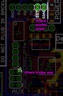
Finding solder bridge using thermal camera

I had a Dexter with the RESET and DIAGNOSE lines tied together somewhere.  I suspected a solder bridge but I couldn't find it.  So I decided to send some current through RESET and DIAGNOSE and get out my thermal camera to see where things were getting hot.  Here's what I saw:

I eventually found the bridge, but was not in the most intense place on the PCB:


In the future, instead of looking for the most intense spot on the PCB, I should observe the path that the heat is traveling.  The fact that the heat was traveling down and left of where I was applying power was a clue that I would find the bridge somewhere along that path.

Monday, June 7, 2021

Esh's Aurunmilla Repair: Strange black lines

 Esh Repair! I almost didn't notice these weird unexplained black lines until I looked closer.


Friday, April 23, 2021

My Rick Dyer interview!

Due to some extremely lucky circumstances, I was able to spend an afternoon with the man who created one of my most treasured childhood memories.  In 1983 Rick Dyer was the catalyst that produced the amazing arcade game, Dragon's Lair.  As a young kid during this time, the memories of seeing this game for the first time in a random pizza parlor in Los Angeles still leave a deep impression upon me.  I had previously met Rick twenty years ago at the Classic Gaming Expo in Las Vegas, NV but it was during an autograph line so I only spoke to him for about ten seconds.  I never expected to talk to him again after that.  But his Dragon's Lair had stopped working so he was referred to me due to my Dexter project and eventually asked me to come fix his Dragon's Lair which he is showcasing at a rental property in Spokane, Washington.  After I fixed the Dragon's Lair, I asked him for this interview and he graciously accepted.

The video of Time Traveler running on Dexter that I mention during the interview is here.

I also asked him several questions in the car which I did not record.  I am paraphrasing his answers below before I forget.

Q: I asked Rick what his background was before Dragon's Lair.  Was he a tech guy? A business guy?

A: Rick said that he had worked on Intellivision titles for another company and had been doing moon-lighting projects on the side.  His side business became so big that he eventually quit his day job and formed his own company.  His company made a lot of handheld games, I believe that little LCD games that I would see kids playing during recess around 1982 when I was in elementary school.  The company was successful and had about 40 employees.  (I found this particularly surprising because I had always imagined that Rick had approached Don Bluth as an individual who had an idea, not as the owner of a successful company of 40 people).  Rick went to school for engineering and preferred to do engineering but as his company grew he was forced into a management role instead.

Q: I asked Rick when he first saw a laserdisc and what gave him the idea to use it in a video game.

A: Rick says he saw it at a trade show and realized that it would be good to use in a video game at that time.  He felt pressure to be first to market with this idea because he was sure someone else would release a product using this idea if he didn't.

Q: I asked Rick about the Thayer's Quest origins and mentioned that I heard it was originally not a laserdisc game.

A: Rick said that Thayer's Quest went through several iterations and used different more primitive technologies before it became a laserdisc game.

Q: I asked Rick what company he hired to do the Thayer's Quest animation.

A: Rick said it was a company in the Philippines.

Q: I asked Rick what the motivation was to have two audio tracks per scene in Thayer's Quest.

A: Rick said it was so that you'd hear something different when you visited the scene a second time.

Q: I asked Rick how he managed to successfully pitch Dragon's Lair to Don Bluth.  Wouldn't Don Bluth be a hard guy to reach and an even harder guy to convince to take on such a risky project?

A: Rick said that he got lucky because Don Bluth's company was looking for another project after Secret of NIMH and Rick was at the right place at the right time.  Rick had previously worked with Cinematronics which is why he approached them to handle manufacturing of the game.

Q: I asked Rick how many people programmed the z80 code for Dragon's Lair.  Was it one guy or a team?

A: A team.

Q: I asked Rick some more details about the production of Dragon's Lair.  Wasn't it insanely expensive to get prototype laserdiscs made?  How did he figure out how to get a laserdisc made?

A: Rick said his team did the research to learn how to get a laserdisc made.  And yes, prototype discs were expensive to manufacture.  Both Don Bluth's company and Cinematronics were in financial peril during the production of Dragon's Lair and the game almost didn't get finished due to money running out at both locations.  The game cost over $1M to create which was unheard of at the time.

Q: I asked Rick why the drawbridge scene is skipped in all versions of Dragon's Lair.

A: Rick didn't remember why.  (I would've shown him a clip to refresh his memory but I was running out of time)

Saturday, April 17, 2021

Dragon's Lair Power Supply Replacement

 I recently followed Shaun Wood's excellent guide to creating a modern replacement for the Dragon's Lair power supply.

After some minor failures, I got it working with a few tweaks to his instructions:

  • The J2 (aka "P2" on his page) connector should have the black wire on pin 1, not the white.  So the pattern should go black, white, black, white instead of white, black, white, black.  This is to be consistent with the internal wiring my both my Dragon's Lair and Space Ace cabinets.  Since it is AC power, polarity may not matter for performance, but for safety it could be important.
  • To minimize observed monitor noise, tie FG and GND together.  Thanks to Brad Oldham for the suggestion.  Here is a random thread I found on the internet on the subject.  Without doing this, my monitor picture was significantly noisy.
  • Model of power supply that I ended up using successfully is Arcity MIN HONG MH-120N-R3 which can be currently purchased from https://www.amazon.com/gp/product/B07RT54H9V/


Friday, January 8, 2021

Dragon's Lair's software watchdog

I've been rewriting Daphne's Z80 emulator (from scratch) and testing it on Dragon's Lair.  I've got it far enough along so that it loops at the disc routine at 0x231 waiting for an LD-V1000 strobe.  While I had it looping, I was checking out some performance metrics to see how fast my new Z80 emu was running.  To my shock, after about 1 minute, program execution moved away from that endless loop.  After a few hours of tracking down why, I discovered this software watchdog that I never knew existed.


(my disassembly below)

ROM:19E3 DecrementWatchdog:                      ; CODE XREF: IRQ+1BC↑j
ROM:19E3                 ld      hl, A0DE_WatchDogCounter
ROM:19E6                 call    DecrementMem16  ; Decrements a 16-bit memory location
ROM:19E6                                         ; Flags are set according to SBC rules.
ROM:19E6                                         ; HL: pointer to 16-bit memory value
ROM:19E6                                         ; DE and BC are clobbered
ROM:19E9                 jr      nc, CheckSoundThenExitIrq
ROM:19EB                 jp      DoSoftReset     ; watchdog has not been fed. we're stuck in an endless loop.


ROM:1FCF DoSoftReset:                            ; CODE XREF: IRQ+1CB↑j
ROM:1FCF                 ld      sp, 0A3FFh      ; blow away all stack info; start over.
ROM:1FD2                 ld      hl, 0A030h
ROM:1FD5                 ld      de, 0A031h
ROM:1FD8                 ld      bc, 3CFh
ROM:1FDB                 ld      (hl), 0
ROM:1FDD                 ldir                    ; this appears to clear mosts of the game data except the boot-up stuff
ROM:1FDF                 call    ResetWatchdogCounter ; resets watchdog counter back to max value (about 70 seconds)
ROM:1FDF                                         ; (this must be called regularly to avoid a soft system reset)
ROM:1FE2                 ei
ROM:1FE3                 jp      loc_1244        ; this is an alternative to "RETI"; essentially giving up on recovering


ROM:1C2D ; =============== S U B R O U T I N E =======================================
ROM:1C2D
ROM:1C2D ; resets watchdog counter back to max value (about 70 seconds)
ROM:1C2D ; (this must be called regularly to avoid a soft system reset)
ROM:1C2D
ROM:1C2D ResetWatchdogCounter:                   ; CODE XREF: START+10↑p
ROM:1C2D                                         ; sub_15B4+F5↑p ...
ROM:1C2D                 ld      hl, 8AAh
ROM:1C30                 ld      (A0DE_WatchDogCounter), hl
ROM:1C33                 ret
ROM:1C33 ; End of function ResetWatchdogCounter
ROM:1C33
ROM:1C34
ROM:1C34 ; =============== S U B R O U T I N E =======================================