Lately I've been getting interested in generating an NTSC video signal from scratch. In order to do this, I need a DAC. But I am not ready to buy a good quality DAC (especially since the one Warren pointed me to was a surface mount!) so I thought I'd mess around on my breadboard with a simple DAC known as an R-2R resistor ladder network.
Actually, before I experimented with this on my breadboard, I tried to figure out how it worked on paper and I got confused. So I arranged it on my breadboard to try to help me understand how it worked better by measuring the voltages at various junction points. I have a better understanding now but still need more info to start generating an NTSC video signal. I am hoping someone more expert than I can help me understand the math involved to finally learn how this dang thing works.
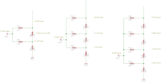
Here are some schematics that represent my experiments.
220 and 115 ohm resistor experiments
I started off using 220 and 115 ohm resistors (230 ohm resistor was not available from digikey so I approximated). This is based on advice I found on this page (I am going to try building on of those things once my PCB from BatchPCB shows up). Although they expert the source to be 3.3V, I was curious to see what would happen if my source was 5V.
Here are the results of my experiment:
First, let me explain a few things. In the setup on the left, I have two source bits (I'll call them D0 and D1) and both are set to "1" (5.04V). So this represents a 2 bit DAC that has 4 possible values (0, 1, 2, and 3). You will notice that the maximum voltage is 3.79V here. This confused me greatly until I re-read the wikipedia page and found this formula:
Vout = Vref × VAL / 2N
What this means is that for a 2 bit DAC, the maximum output voltage can only be 75% of the output voltage. Why? Because 2^2 is 4, and the maximum value (VAL in the equation) is 3. So 5.04 * (3/4) is indeed 3.78V; conclusion? Trying to use a 2-bit DAC is a crappy idea :)
You will notice that as I add bits, the maximum voltage increases. In the middle layout, where I have 3 input bits (again all 1's), the maximum voltage is 4.43V . 2^3 is 8, so 5.04 * (7/8) is 4.41V so we are pretty close.
On the right layout, I have 4 bits, and the maximum voltage is 4.74V. 5.04 * (15/16) is 4.725V so we are still pretty close.
4.7k and 10k ohm resistor experiments
It turns out that the resistor values themselves don't seem to matter much as long as they are approximately 2:1 to each other for the type of experiment that I am doing.
I got almost the same results using 4.7k and 10k resistors:
How to output to a range of 0V-1V for NTSC signal?
So, this is what I am still trying to figure out.
I've seen that TV's are supposed to have an internal 75 ohm resistor. And apparently it is possible to use this fact and choose resistor values in one's R-2R network such that the resulting voltage is between 0-1V so that it is in spec for a TV signal. On this page, it says: "the resistor values are chosen to turn the 3.3V of the Papilio output into the 0, 0.3 and 1.0V under 75 ohms that the tv requires." but I don't understand how they figured out which resistor values to use!
Also, on this page, the guy is using 450 and 900 ohm resistors with a 5V source (although he isn't quite doing the same layout I was). So obviously there is some math here that I am missing. If someone could enlighten me, I would be grateful!


No comments:
Post a Comment